IoT Smart RFID Door Lock System Using NodeMCU ESP8266 Circuit Diagram Building a smart door lock using a Raspberry Pi is an exciting and rewarding project that can enhance the security and convenience of your home. Throughout this guide, we have explored the step-by-step process of creating a smart door lock, from choosing the right hardware to programming the Raspberry Pi and assembling the components.

RFID is useful to identify people, to make transactions, etc. You can use an RFID system to open a door. For example, only the person with the right information on his card is allowed to enter. In this tutorial, we have multiple RFID tags, each with its own Unique Identification (UID) but only one card will be granted access. RFID-RC522 Pin Layout Here, we'll focus mainly on the newer NFC standard for RFID chips, and its applications to access control within smart door locks. NFC Smart Locks: How They Work The Tech in NFC Smart Locks. As we've covered the science behind NFC tech in the article referenced above, here we'll mainly discuss its applications in Smart Locks.

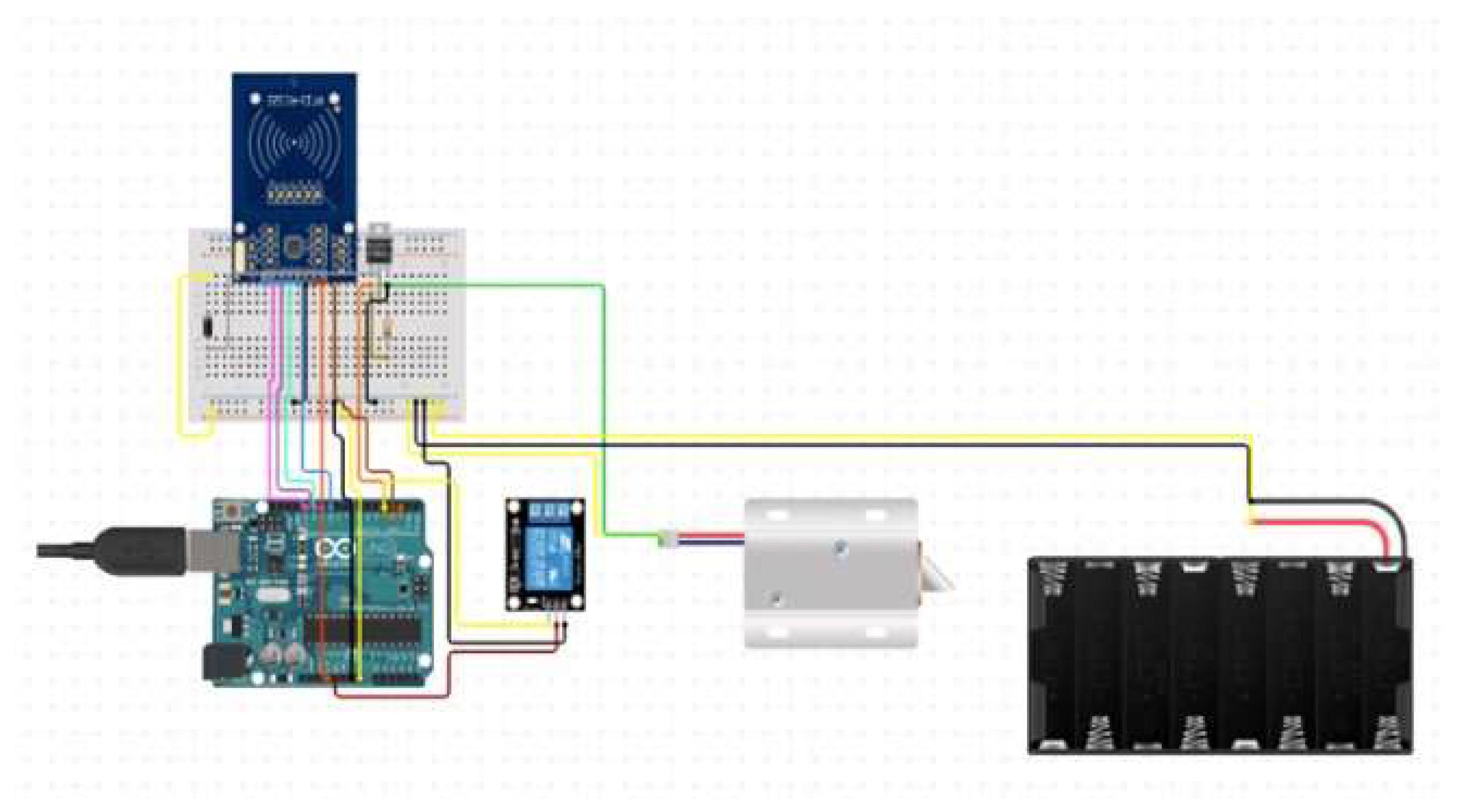
RFID/NFC Door Lock System Circuit Diagram
See how we built it, including our materials, code, and supplemental instructions, on Hackster.io: https://www.hackster.io/hackershack/smartphone-connected-h
Here's what you'll need to create your smart door lock system. Smart Lock Mechanism. Start with a smart lock mechanism that forms the core of your setup. This component includes the locking mechanism, connectivity features, and compatibility with smart home systems. When it comes to selecting the appropriate smart lock technology for Door Lock system. c_cpp. Final sketch, after the test code. 1 //Including Libraries 2 #include < SPI. h > //SPI Library 3 #include < Wire. h > 4 //Include the Wire Library 5 #include < MFRC522. h > //Library of the RFID Module 6 #include 7 < Stepper. h > //Library for the Stepper Motor 8 #include < Adafruit_GFX. h > //Library 9 for the OLED
RFID NFC Door Lock System Circuit Diagram
Hello guys, Welcome to Robocraze! In this video, we have shown the Making of the Smart Security Lock System using the Witty Fox NFC module and Solenoid Lock. This is a door lock security system made with Arduino. Jul 22, 2017 • 172264 views • 33 respects. smart appliances. security. Components and supplies. 1. Servos (Tower Pro MG996R) 1. LED (generic) 1. Buzzer. 1. Arduino Mega 2560. 1. Standard LCD - 16x2 White on Blue. 25. Jumper wires (generic) Project description.
